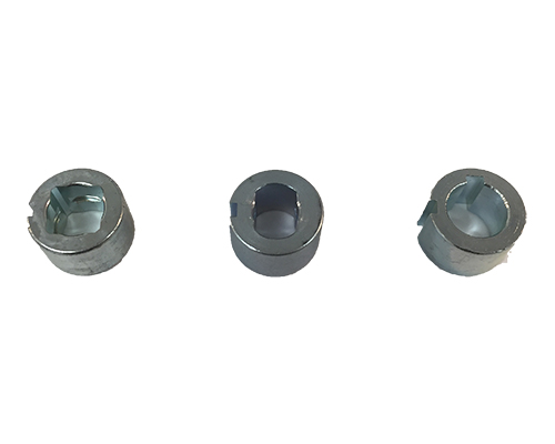
Drive inserts
Match the valve stem profile and dimensions to the selected actuator. Compare EVA drive sizes and mounting patterns →

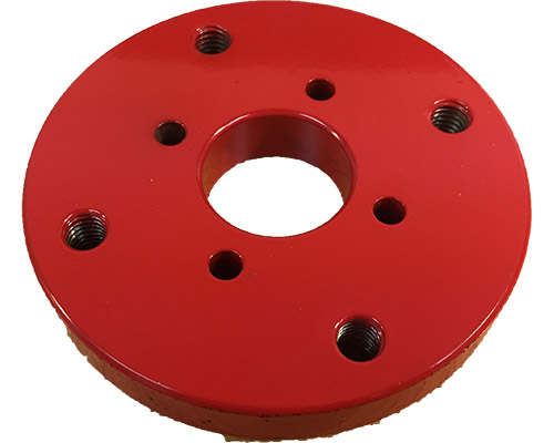
Mounting hardware below the actuator.
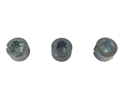
Easytork mounting options include drive inserts, mounting brackets, shafts and spacer plates. Verify the specific interface before assembly; do not use force to compensate for a dimensional mismatch.
Product specifications →Match the valve stem profile and dimensions to the selected actuator. Compare EVA drive sizes and mounting patterns →
Review mounting pattern, alignment, height and support requirements.
For brackets above the actuator, see limit-switch brackets →
Check engagement, fasteners, alignment and freedom of movement using the applicable instructions.
Specifications, dimensions and installation instructions.
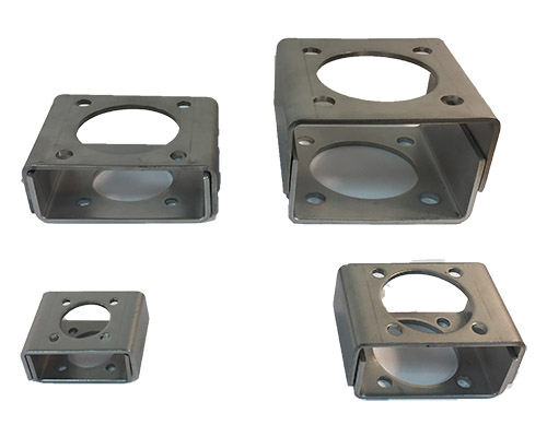
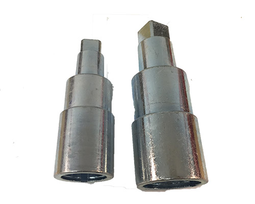
Confirm stem engagement, alignment and clearance for the selected mounting arrangement.
Loads the external video player only when selected. No autoplay.
Watch on Youtube →