
How the Easytork system works.
Vane design, stored air and matched controls. Designed together to make stored-air actuation easy to use.
Select a numbered circle to explore that part.
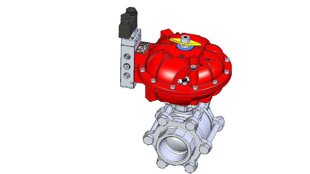
The complete assembly. Select a part to look inside.
Open image full-size ↗THE COMPLETE SYSTEM
Stored-air advantages. Made easy.
An efficient vane actuator, onboard air reservoir and matched controls become one easy-to-use package. Explore each part to see where the benefits come from.
- Compact & fastEfficient vane motion and stored-air return support a smaller package, with less moving air and responsive operation.
Compare size & weight
Spring-return actuators must be sized to compensate for the torque used to overcome their springs. Easytork combines efficient vane motion with stored-air return, supporting a smaller actuator for the required fail-safe torque. A compact actuator requires less air to move, helping it achieve fast stroke times. Actual response depends on actuator size, valve load, supply pressure and control flow; the EVA data below provides the tested reference conditions.
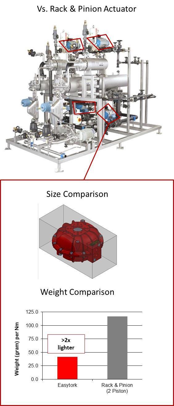
Published size comparison: Easytork and a spring-return rack-and-pinion actuator. Review compact installation considerations → See the before-and-after installation photographs in the gallery →
View EVA stroke-time data
Measured EVA response by model and airflow arrangement. Test conditions are shown with the data.
Stroke time (seconds per direction)
Actuator model Standard ports Standard ports + QEV Factory custom ports + QEV EVA0411 0.24–0.27 Not published Not published EVA0514 0.36–0.39 0.10–0.15 Not published EVA0717 0.45–0.47 0.20–0.25 Not published EVA1022 0.59–0.60 0.48 Not published EVA1227 0.75–0.84 0.5–0.7 Not published EVA1436 1.34–1.47 0.65 0.54–0.57 EVA1646 3.30–3.41 1.10 0.70 Notes
Testing: Cv 1.8, standard for Easytork solenoid and pilot valves; on/off operation, no load, at 80 psi air supply.
Explore fast valve response and the full application table →
- Simpler to stockKeep one EVA actuator platform across operating duties and compatible valve brands. Configure double-acting, fail-open or fail-close with matched controls, and choose the flange pattern and drive insert for direct mounting.
Watch the function change
See function changes on the same platform
EASYTORK IN ACTIONFunction changes on the actuator platform
Loads the external video player only when selected. No autoplay.
Watch on Vimeo →See how the same platform adapts to more valve brands and operating duties: One actuator. More possibilities. →
- The power of standardizationOne actuator body brings mounting and function choices together: direct mounting across compatible valve brands, with double-acting or fail-open / fail-close operation configured through matched controls.
See the integrated system
SEPARATE COMPONENTSA custom assembly project.
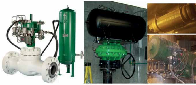
External reservoirs, trip components and connecting pipework.
STANDARDIZED EASYTORK INTEGRATIONDesigned to work together.
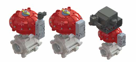
Actuator and reservoir in one body. Application-matched controls on a standardized interface.
Benefits of a Springless Vane Actuator: the detailed standardization write-up →
Put the complete system to work for your valve. Use the selector to bring operating duty, torque, air supply and mounting dimensions together.
02 · VANE CHAMBER
Pressure becomes rotation. Directly.
Air enters through standard NAMUR service ports and acts on the vane inside the working chamber. These ports are integrated into the actuator face on EVA-0411 through EVA-1436; EVA-1646 uses external tubing. The black vane and shaft rotate together in rotary-to-rotary movement, without a linear-to-rotary conversion.
- Efficient rotary torqueThe vane turns air pressure directly into output torque, helping reduce size, weight and air consumption.
- Fewer moving partsOne main moving actuator part replaces a linear-to-rotary conversion mechanism.
Watch the rotary mechanism demonstrations
EASYTORK IN ACTIONOne moving part: mechanism demonstration
Loads the external video player only when selected. No autoplay.
Watch on Vimeo →EASYTORK IN ACTIONPure rotary-to-rotary movement
Loads the external video player only when selected. No autoplay.
Watch on Vimeo → - Seals shaped for rotationLip-seal geometry follows the vane’s rotary movement.
Compare lip seals and O-ring examples
Lip seals designed for rotary motion.
The vane’s lip-seal arrangement works with its rotary motion. The comparison below shows the vane assembly alongside O-ring examples; seal geometry, material, pressure and duty determine suitability.
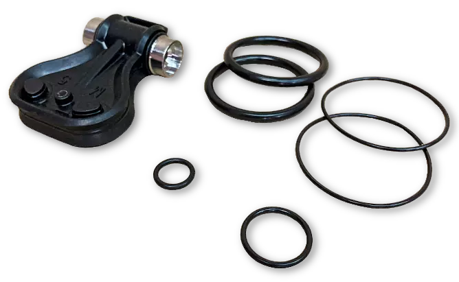
Vane lip-seal assembly and O-ring examples. Open full-size figure →
See how vane geometry turns pressure into torque and how torque varies through the stroke.
03 · ONBOARD AIR RESERVOIR
Stored air, instead of a return spring.
The integral reservoir charges during operation. Matched controls release that stored air for the configured fail-open or fail-close stroke.
- Keep ambient contamination outThe closed-loop fail-safe arrangement avoids drawing outside air into a vented spring chamber.
Compare the airflow demonstrations
Compare the demonstrated ambient-air pathways: spring-chamber breathing versus Easytork’s stored-air return.
SPRING-RETURN COMPARISONAmbient-air breathing
Smoke makes the ambient-air pathway visible in the spring-return example.
Watch on Vimeo →EASYTORK IN ACTIONStored-air return, outward exhaust
Packing peanuts show outward airflow during cycling and loss of air in the Easytork demonstration.
Watch on Vimeo →Springless return. Fewer spring-related concerns.
Stored-air return eliminates return-spring fatigue and corrosion from the actuator’s return mechanism. Other components still require inspection and maintenance for the application.
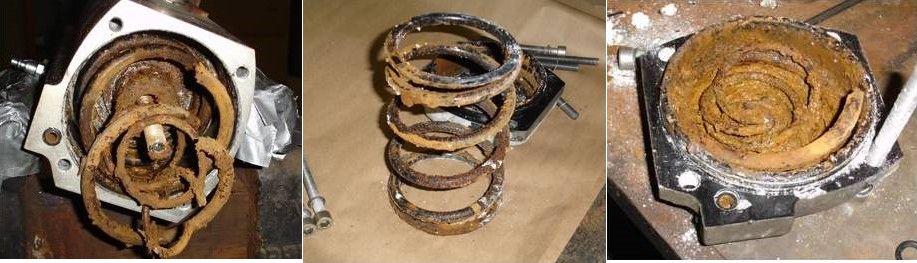
Examples of damaged return springs. Open full-size figure → - Efficient fail-safe torqueStored air eliminates the need to upsize the actuator to overcome spring torque, enabling a smaller actuator for the same required fail-safe torque.
See how stored-air return works
How the reservoir charges and returns the actuator
Supply air powers normal movement and charges the integral reservoir. When the selected fail-safe controls trip, stored air drives the configured fail stroke. Select output, air supply and controls together for the required duty.
EASYTORK IN ACTIONReservoir and solenoid-control demonstration
Loads the external video player only when selected. No autoplay.
Watch on Vimeo → - Low-pressure flexibilityWork with the available air supply without selecting or changing spring packs.
See low-pressure operation
Application evidence includes P/P control systems rated to a maximum of 35 psi and approximately 30 psi demonstrations.
Size the actuator using output at the actual minimum pressure, valve torque, required fail action and compatible controls, within the selected model’s operating limits.
Low-pressure selection workflow → Low-pressure application case PDF →
Compare stored-air and spring-return energy, including the air path through the actuator.
04 · STANDARDIZED CONTROL INTERFACE
From custom pipework to an easy NAMUR-based connection.
Easytork actuators are designed around NAMUR actuator service ports, with a separate air reservoir port for the integrated reservoir connection. Stored-air actuation no longer has to be an ad hoc assembly project.
- Designed to fit togetherThe actuator and accessory have matching reservoir connections, reducing custom piping and integration work.
- Change the actionConfigure double-acting, fail-open or fail-close using the appropriate control accessory.
- One configurable platformMatched accessories simplify configuration and stocking.
Choose your control arrangement
1 Open or close
2 Modulating / throttling
Match the controller, pneumatic connections and auxiliary mounting interface to the required function.
ESV, EPV, and NTV reservoir fail-safe control principles →
Control and accessories interface →
05 · VALVE COUPLING
A close connection. Coordinated movement.
Multiple bolt circles and adaptable drive inserts make the vane actuator easier to mount directly to a valve. A closely fitted insert reduces looseness between actuator and valve.
- More mounting choicesThe standard EVA platform adapts easily to a broad range of valves through multiple bolt circles and adaptable drive inserts.
View mounting and direct-coupling examples
EASYTORK IN ACTIONDirect-mount and valve-adaptation demonstration
Loads the external video player only when selected. No autoplay.
Watch on Vimeo → - Precise rotary trackingRotary-to-rotary movement avoids the play introduced by a linear-to-rotary conversion. Custom coupling on ECA control-service configurations provides a tight valve-shaft fit, helping the valve track actuator motion.
View independent positioning results
Direct coupling in control service
Custom ECA, ECA-IC and ECA-F coupling configurations closely fit the rotary valve shaft, reducing connection slack. These control-service interfaces complement the vane’s direct rotary-to-rotary movement.
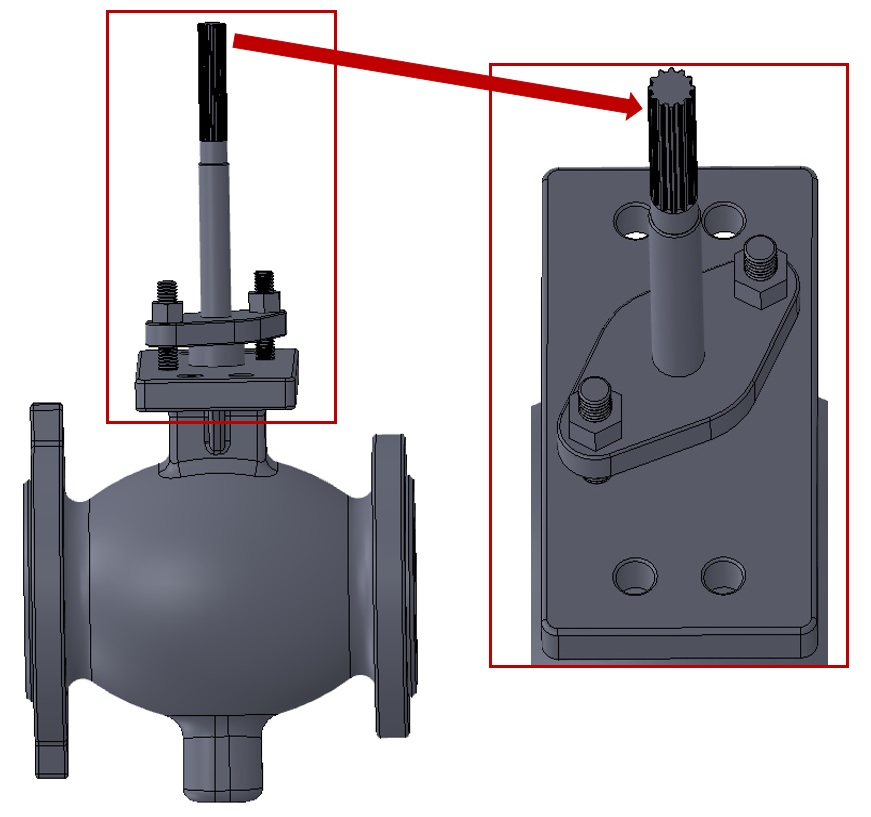
ECA-F: splined-shaft application reference. Open full-size figure → 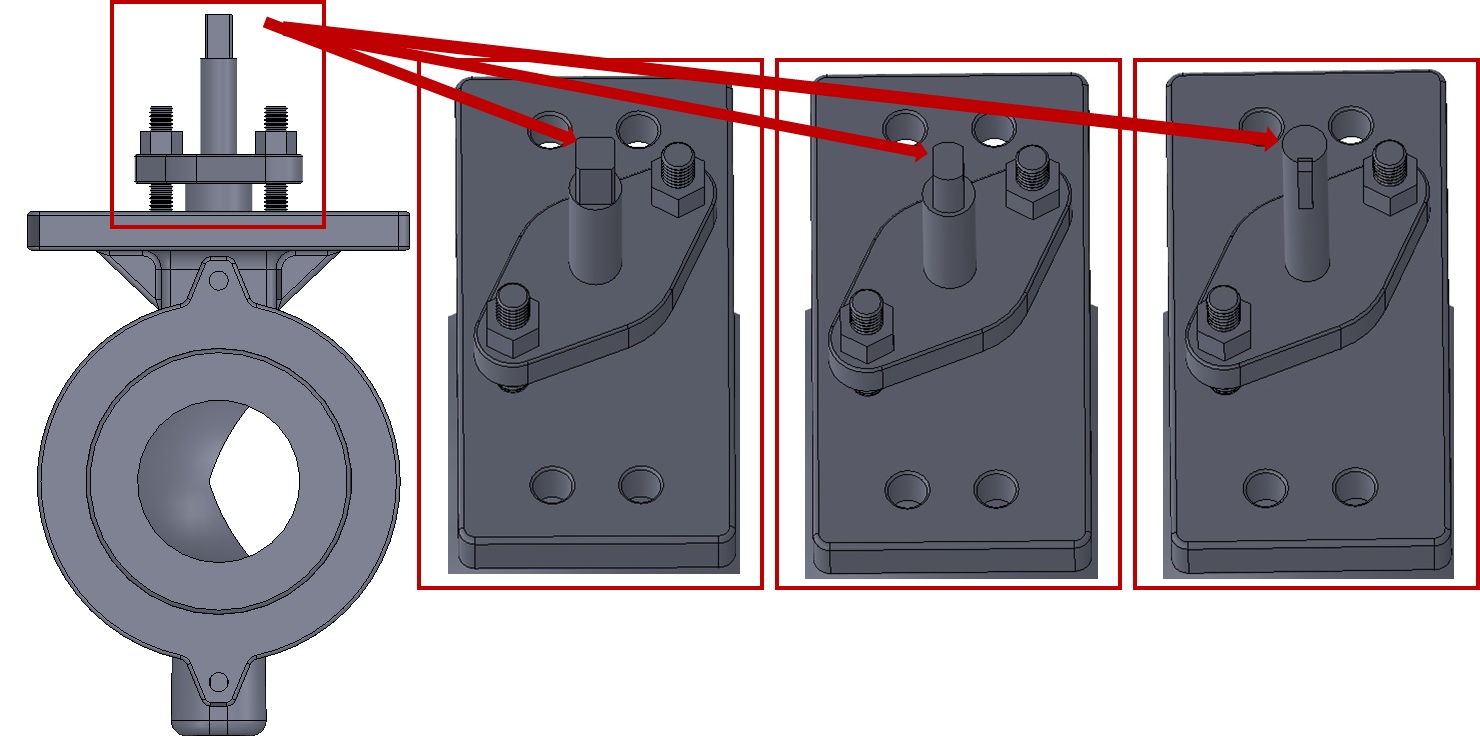
ECA-IC: square, double-D and bore-and-key interface references. Open full-size figure → These records describe custom-coupled ECA valve-actuator assemblies, not standard EVA performance. Third-party BenchMark diagnostic evaluations measure the tested valve-actuator assemblies. Explore their response plots, setup annotations and results below.
ECA-F positioning-system HDRL record
Test configuration: a 4-inch segmented valve, ¾-inch spline shaft and ECA-07. Hysteresis plus deadband, repeatability and linearity are reported separately in percent of full stroke.
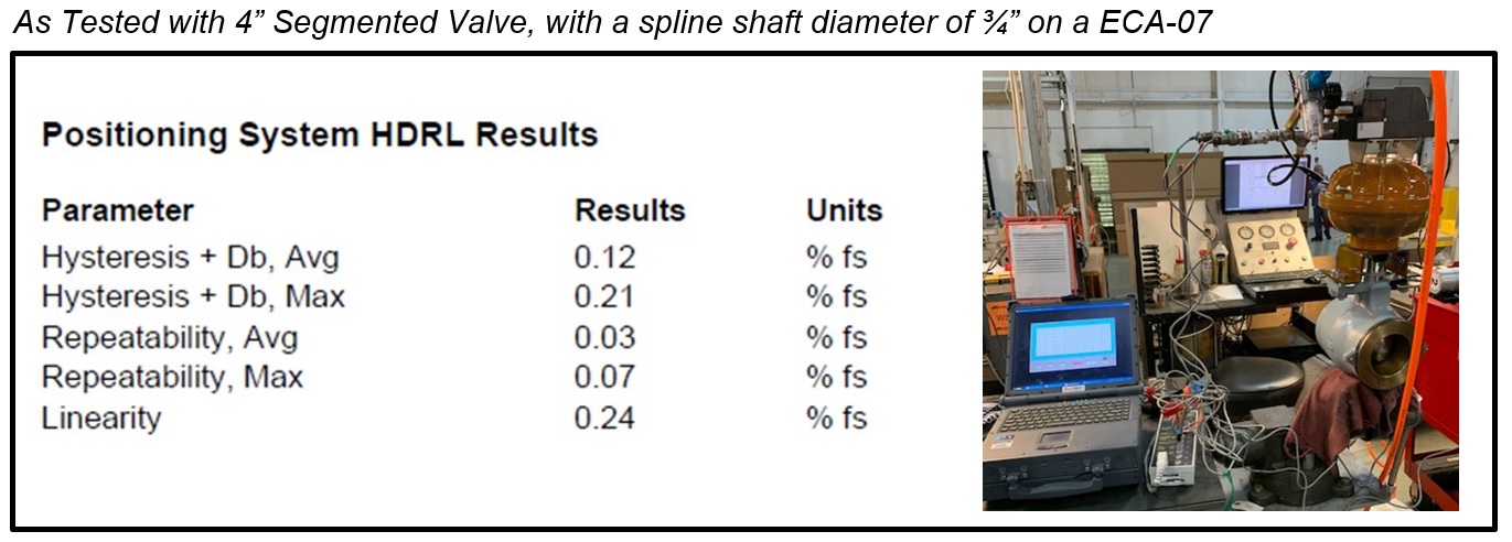
Test configuration: 4-inch segmented valve, ¾-inch spline shaft, ECA-07. Open full-size figure → ECA-IC detailed response plots
Explore step resolution, deadband, step sensitivity and overall valve performance in the ECA-IC response plots.
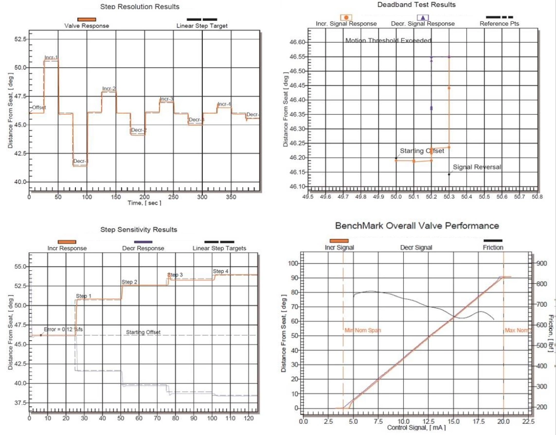
ECA-IC response plots: step resolution, deadband, sensitivity and overall performance. Open full-size figure → ECA-IC hysteresis, deadband and lag
The separate ECA-IC summary defines HDL as hysteresis, deadband and lag-not linearity. The evaluation’s acceptance criteria and comparisons are shown in the figure below.
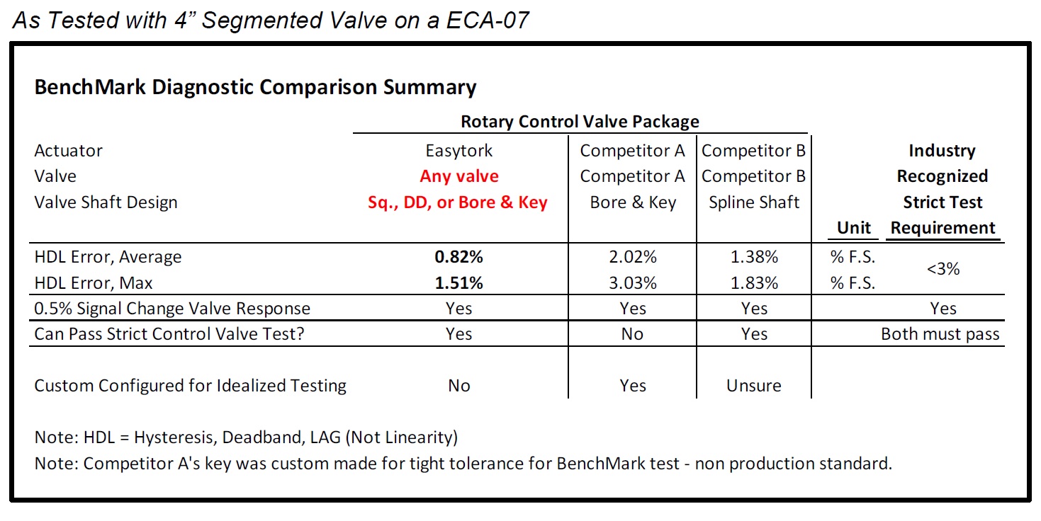
Tested arrangement: 4-inch segmented valve with ECA-07. Results and comparisons shown apply to that assembly. Open full-size figure → Match the actuator and positioner to your control duty. Actual shaft movement and response under changing loads provide the practical measure of control performance.
Define the control-duty acceptance criteria → ECA interfaces, assembly and product references →