
Match the interface.
Not just the bolt circle.
Four checks establish whether an actuator can mount directly to a valve. The drive connection also matters when the application calls for precise positioning.
Two interfaces must work together
The mounting flange supports the actuator on the valve. The drive connection transfers torque from the actuator to the valve stem. A matching bolt-hole pattern does not, by itself, establish a compatible assembly.
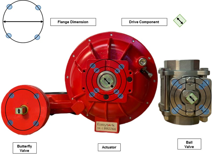
Direct mounting joins the valve and actuator without intermediate support. Where the interfaces do not match, an appropriately designed bracket, coupling or other mounting hardware may be required.
Four checks for direct mounting
All four conditions must be satisfied for the selected valve and actuator combination.
1. A suitable mounting face
The valve needs a flat mounting surface that allows the actuator to seat correctly. A packing gland or other feature projecting above the flange can interfere with direct mounting even when the bolt holes line up.
Use the valve manufacturer’s drawing to check the mounting face and surrounding clearance.
2. A matching flange pattern
Compare the valve’s bolt-circle diameter and hole pattern with the selected actuator’s mounting drawing. ISO 5211 provides a standardized reference for part-turn actuator-to-valve interfaces, but actual valves can also use non-ISO patterns.
Easytork provides ISO and selected non-ISO mounting patterns across its product range. Compatibility is model-specific: a pattern available on one actuator size is not automatically available on every size.
3. A compatible drive shape and size
The valve stem must fit the selected actuator drive component in both geometry and dimensions. Common forms include square, Double-D and bore-and-key connections. A standard square insert does not automatically fit a different square dimension or another stem shape.
In Easytork’s drawing notation, for a square drive, V is the width across flats. For a Double-D drive, V is the overall width and V1 is the flat-to-flat dimension. For bore-and-key, V is the bore diameter, V1 is the key’s overall width and V2 is the key’s overall depth, not only its projection beyond the bore.
Use the reference below for checks 2 and 3: compare the flange pattern and the drive size separately.
ISO and Common Industry Flange Patterns and Drive Sizes
| Flange / pattern | Bolt circle, mm | Bolt circle, in | ISO square across flats, mm | Other drive |
|---|---|---|---|---|
| ISO F03 | 36 | 1.42 | 9 | |
| ISO F04 | 42 | 1.65 | 9, 11 | |
| ISO F05 | 50 | 1.97 | 9, 11, 14 | |
| ISO F07 | 70 | 2.76 | 11, 14, 17 | |
| Common non-ISO | 82.6 | 3.25 | - | |
| ISO F10 | 102 | 4.02 | 14, 17, 19, 22 | |
| ISO F12 | 125 | 4.92 | 17, 19, 22, 27 | |
| Common non-ISO | 127 | 5.00 | - | |
| ISO F14 | 140 | 5.51 | 22, 27, 36 | |
| ISO F16 | 165 | 6.50 | 27, 36, 46 | |
| ISO F25 | 254 | 10.00 | 36, 46, 55 | |
| ISO F30 | 298 | 11.73 | 46, 55, 75 |
Bold: ISO 5211 preferred square-drive sizes.
ISO reference: ISO 5211:2001, §5, Table 2 (bolt circle d3), and §7.3, Table 5 (square-drive sizes and preferred dimensions). This is the edition used for this reference table; ISO 5211:2026 is the current edition.
Common industry non-ISO patterns from Easytork’s handbook.
4. Enough space for the valve stem height
The actuator must accommodate the projecting stem height while seating on the valve mounting face. A stem that fits the opening can still be too tall, leaving an unintended gap between the mounting faces. Do not use the mounting bolts to force incompatible parts together.
Start an actuator selection review
Choose a known valve, mounting review or torque sizing route. Each can be considered independently.
Actuator Selection →Mounting adaptability and coupling precision are different goals
EVA uses adaptable drive inserts for different valve interfaces. ECA uses a fixed, application-specific coupling where close fit and precise positioning are the priority.
Understand what the drive fit contributes
Clearance in the connection can allow some actuator movement before the valve stem follows when rotation changes direction. The fit therefore matters alongside actuator and positioner performance.
EVA uses interchangeable inserts to accommodate multiple stock sizes and custom profiles. ECA uses one fixed, application-specific drive connection for the selected valve, rather than EVA’s interchangeable stock insert arrangement. The valve, drive connection, actuator and positioner together determine the assembly’s positioning performance.
Direct mounting describes the physical mounting arrangement. It does not, on its own, establish a quantified positioning-accuracy result.
When intermediate support is needed
A bracket and coupling can connect interfaces that cannot mount directly. Their dimensions and alignment need to suit the valve stem, actuator drive and required load. Poor alignment or excess clearance can introduce side-loading or lost motion; those are assembly considerations, not an automatic outcome of every bracketed installation.
Bring the dimensions that resolve the fit
- Valve manufacturer, model and mounting drawing.
- Mounting face and any projecting packing-gland features.
- Bolt-circle diameter, hole pattern and fastener details.
- Stem shape and complete drive dimensions, including flats or keyway.
- Stem height above the mounting face.
- Required torque, operating function and any positioning requirement.
These details let us evaluate direct mounting, an appropriate insert, or intermediate hardware without assuming that a shared flange label guarantees fit.
EVA direct mounting in practice
A compatible EVA direct-mount connection removes the need for an intermediate bracket and coupling. The mounting face, flange pattern, drive profile and available stem depth must still match the selected valve.
Technical references
Contact us about the handbook →
EVA model documents · Drive inserts and mounting hardware · Catalogue valve-interface summary
Work through the valve interface
Send us the valve drawing and the duty you need. We can review the mounting and drive arrangement with you.
Contact us →