Home/Products & technical data/ECA series
ROTARY CONTROL ACTUATOR

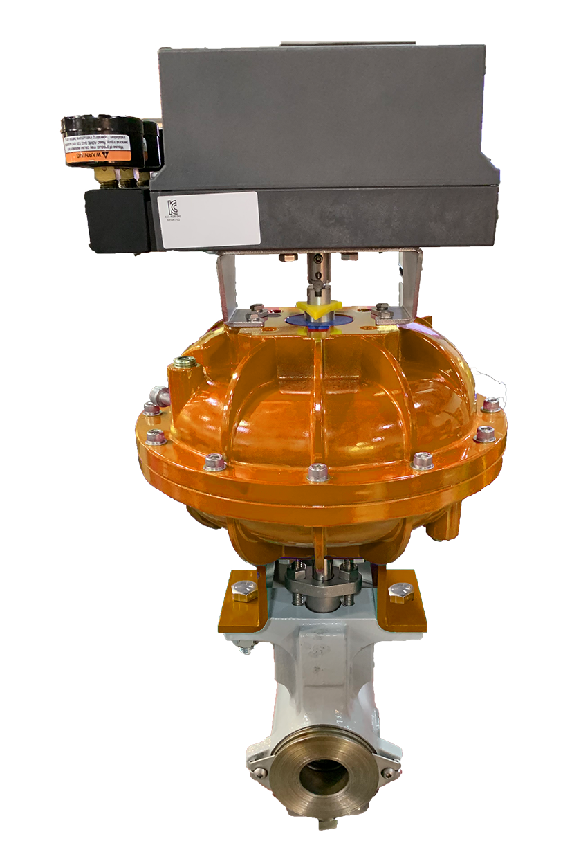
ECA rotary control valve actuators

Quarter-turn vane actuation for rotary control valves. Choose the shaft interface for your valve, then pair the actuator with its positioner and fail-action controls.

ECA series
Control-valve actuation

Direct rotary drive.
Two shaft interfaces.

The ECA uses rotary vane motion rather than converting linear travel through a linkage. The June 2021 catalog describes a solid connection from the positioner to the valve stem. How drive fit affects valve-stem tracking →

ECA-F

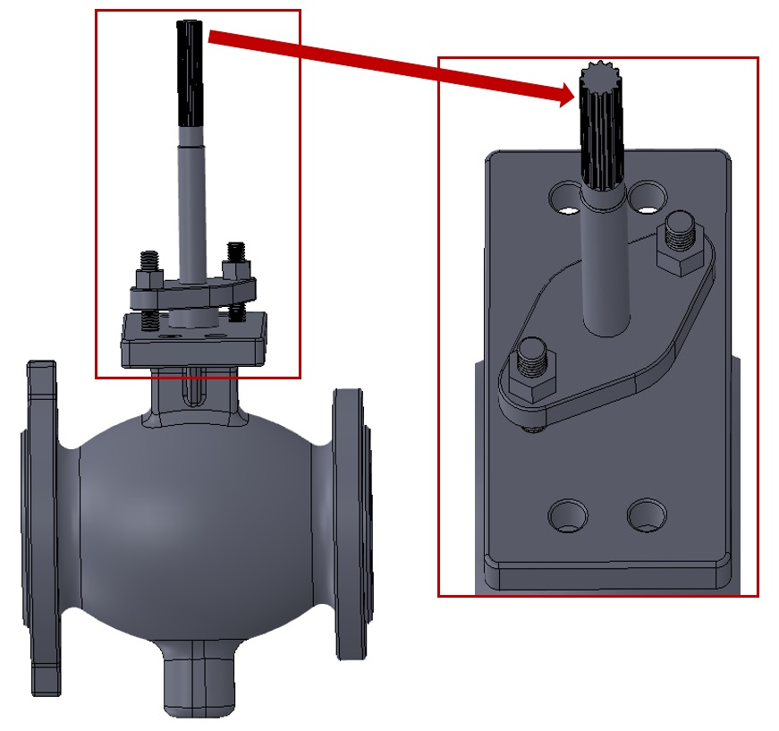
For valves with splined shafts.

ECA-IC

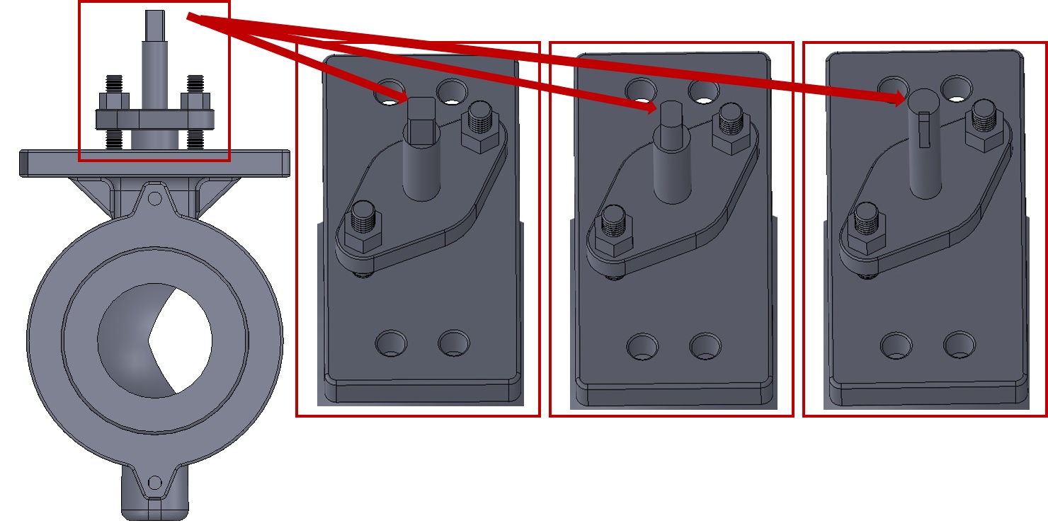
For square, double-D, or bore-and-key valve shafts.

A double-acting positioner controls normal travel. For fail-safe service, use the specified NTV arrangement and fail direction.

Technical self-service

Documents &
dimensions.

Specifications, dimensions and installation instructions.

Interfaces & assembly

See how the actuator meets the shaft.

ECA-F splined-shaft interface
ECA-F shaft-interface detail. Open full-size figure →
ECA-IC square, double-D and bore-and-key shaft interfaces
ECA-IC interface alternatives. Open full-size figure →
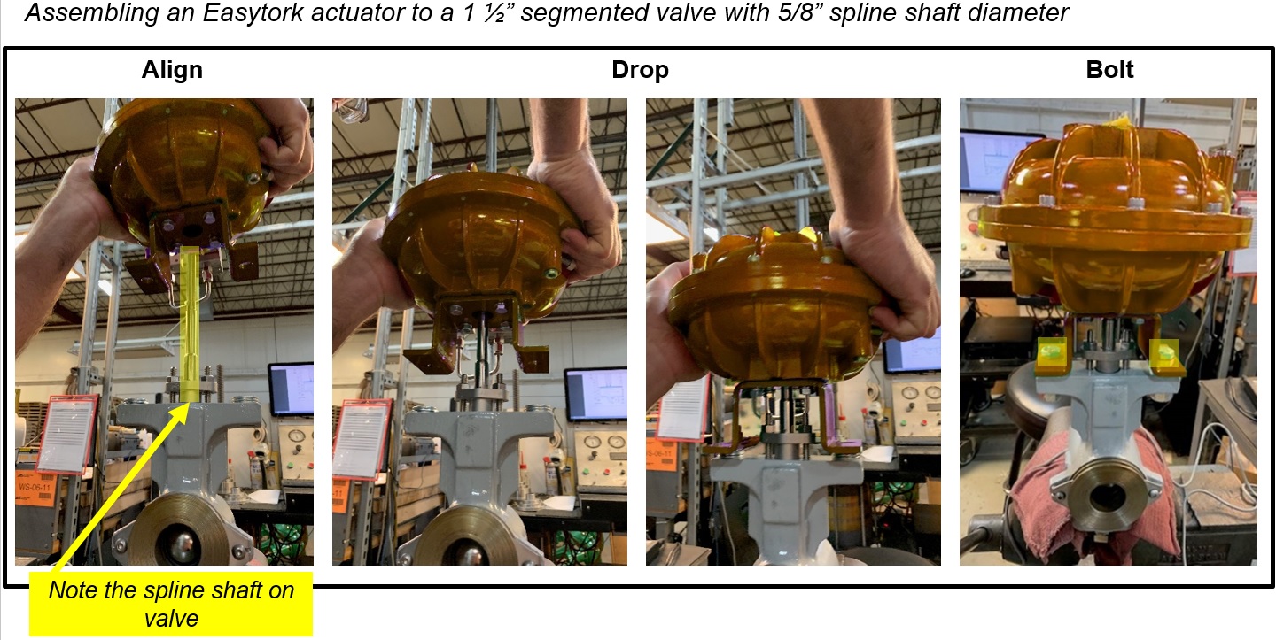
Published ECA-F assembly sequence
ECA-F assembly illustration. Follow the applicable IOM and verified dimensions. Open full-size figure →
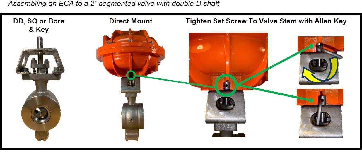
Published ECA-IC assembly sequence
ECA-IC assembly illustration. Confirm alignment and engagement before fastening. Open full-size figure →
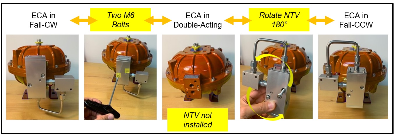
Published ECA function arrangement
Original ECA function arrangement; confirm the selected NTV/positioner and fail direction. Open full-size figure →

Torque reference

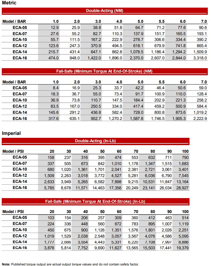
Published ECA torque chart
ECA torque chart: pressure, normal output and minimum end-of-stroke fail-safe output; no safety factor included. Open full-size figure →

Independent test evidence

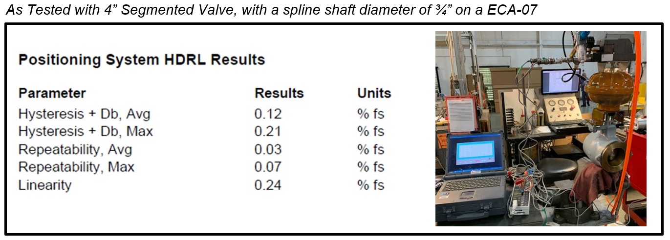
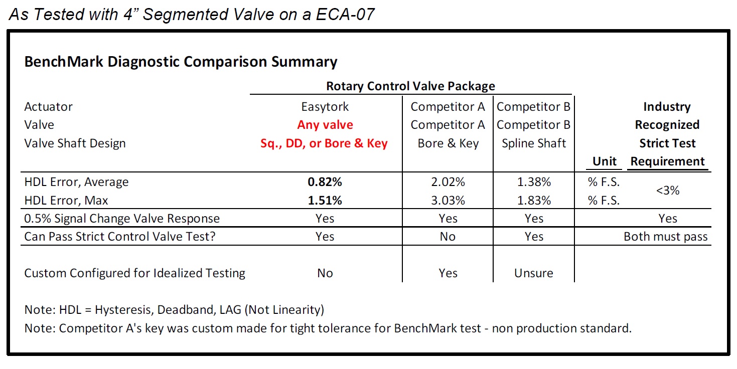
ECA-F HDRL positioning result
4-inch segmented valve, ¾-inch spline shaft, ECA-07; test configuration. Open full-size figure →
ECA-IC HDL result
HDL here means hysteresis, deadband and lag, not linearity. See the test configuration and response plots below. Open full-size figure →
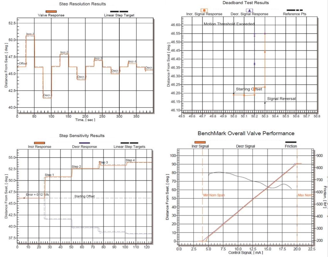
ECA-IC diagnostic response plots
Original plots; full setup/date not supplied within the graphic. Open full-size figure →

Read the metric distinctions and limitations →

EASYTORK DEMONSTRATION

ECA control-actuator summary

Loads the external video player only when selected. No autoplay.

Watch on Youtube →
EASYTORK DEMONSTRATION

ECA control-actuator overview

Loads the external video player only when selected. No autoplay.

Watch on Youtube →
Application support

Bring the duty.
We’ll work through the actuation.

Torque, air supply, operating conditions and the action you need.

Selection checklist

What we need to review.

  • Valve model, shaft and mounting drawings
  • Travel and torque through the working range
  • Positioner and signal requirements
  • Fail direction and acceptance criteria