
Three control paths.
One stored-air principle.
How the ESV, EPV and NTV connect a control command to Easytork reservoir fail-safe actuation.
Separate the command from the energy
Choosing a control arrangement? Explore the Control interface and compare open/close or modulating arrangements →
A control signal tells a valve where to go. Compressed air supplies the energy that turns the actuator. In an Easytork reservoir fail-safe arrangement, part of that pneumatic energy is stored in the connected air reservoir for a configured fail stroke if the air supply is lost.
Three functions work together: the reservoir stores air, check-valve action prevents that air from escaping back into the failed supply, and the control accessory routes it to the actuator.
The choice of accessory depends on how normal operation is commanded: electrical on/off control, an external pneumatic pilot signal, or a double-acting positioner.
The actuator interface: two service ports, plus stored air
P2 and P4 are the actuator service ports. They form the NAMUR pneumatic interface used with standard NAMUR-mount 5/2 solenoid valves for double-acting operation. Select the valve and mounting arrangement for the actuator model, pressure and required airflow; the standard 5/2 connection alone does not provide reservoir fail-safe control. Applying pressure to one side while allowing air to leave the other produces rotation. Dedicated Air Res. porting provides the charging and discharging path for the reservoir.
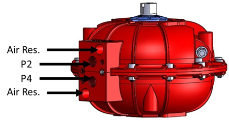
During normal operation, the actuator works through P2 and P4 as a double-acting actuator, while the reservoir is maintained as stored pneumatic energy. The matched control accessory combines that interface with the required command method. The reservoir supplies the energy for the fail stroke; it is not a second position command.
ESV: electrical on/off control
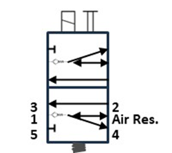
The Easytork Solenoid Valve has a 5/2 solenoid valve at its core: five ports and two switching positions. During normal operation, it supplies one actuator chamber while exhausting the other. The Easytork arrangement also provides the reservoir charging and fail-safe air paths.
The electrical command operates the solenoid; supply air does the mechanical work. On loss of air supply, stored reservoir air is used for the configured fail stroke. ESV installation orientation sets the actuator’s clockwise or counter-clockwise fail action; the installed valve arrangement determines whether that rotation is fail-open or fail-close.
ESV connections and operating sequence
Read the connections
- P1: incoming supply air.
- P2 and P4: the two actuator service connections.
- Ports 3 and 5: exhaust connections for the opposite actuator chamber.
- Air Res.: reservoir connection, separate from the basic 5/2 port layout.
Normal service
The solenoid alternates supply pressure between P2 and P4. The opposite chamber vents through an exhaust path, so the actuator can move in either direction. At the same time, the reservoir charges and is maintained at supply pressure.
When supply pressure is lost
- Pressure at P1 falls.
- The internal check valve behind P1 closes, retaining the stored reservoir air.
- In the illustrated arrangement, reservoir air is routed internally to P4.
- That air drives the actuator to the configured fail position.
The P4 designation describes the illustrated control path, not a universal statement that every process valve closes in that direction. The installed orientation and valve coupling establish fail-open or fail-close action.
EPV: an external 3/2 solenoid provides the pilot signal
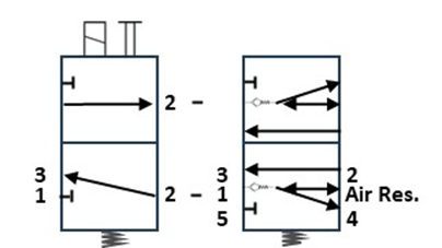
The Easytork Pilot Valve has a 5/2 pilot valve at its core. An external 3/2 solenoid supplies or vents its pilot signal; the EPV directs the actuator’s main airflow. This separates the third-party electrical control device from the Easytork reservoir fail-safe routing.
The EPV interfaces any non-NAMUR-mount third-party 3/2 solenoid valve with Easytork fail-safe actuation. Remote or nipple-mounted arrangements give flexibility in where that solenoid is installed. EPV installation orientation selects clockwise or counter-clockwise fail action; the valve assembly determines whether that rotation opens or closes the process valve.
EPV connections and operating sequence
Separate pilot flow from actuator flow
The EPV uses the same principal port layout: P1 supply, P2 and P4 actuator service, ports 3 and 5 exhaust, and Air Res. reservoir porting. Its switching command is pneumatic rather than a coil acting on the EPV itself. The pilot signal is typically derived from the supply entering P1.
Apply and remove the pilot signal
- The external 3/2 solenoid applies a pneumatic pilot signal.
- The EPV shifts and routes the main supply to the appropriate actuator service port, exhausting the opposite side while charging the reservoir.
- When the pilot signal is removed, the pilot valve returns to its spring-biased state. Reservoir fail-safe capability remains available.
The pilot-valve bias spring is a control-device feature. It is not a spring pack providing the actuator’s fail-stroke energy.
When supply pressure is lost
The internal check valve closes to retain reservoir air. The control arrangement then routes this stored air to drive the configured fail stroke. Removing a pilot command during normal supply and losing the air supply are distinct events, even when the application requires the same final valve position.
NTV: position normally, fail in a defined direction
For modulating service, a double-acting positioner controls normal actuator travel. The Easytork NAMUR Trip Valve adds the reservoir fail-safe air path; it does not replace the positioner or generate the position command.
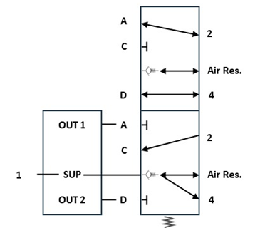
The NTV is universally compatible with any double-acting positioner. In normal operation, the positioner’s two pneumatic outputs pass through the NTV to the actuator. On loss of supply air, the NTV routes stored reservoir air for the configured fail stroke. The command signal, such as 4–20 mA or 3–15 psi, belongs to the selected positioner, not to the NTV itself.
NTV connections and operating sequence
Connect the positioner to the trip valve
- Positioner Out 1 → NTV A: control pressure for one side of the actuator.
- Positioner Out 2 → NTV D: control pressure for the opposite side.
- NTV P2 and P4: actuator service connections.
- P1: primary air supply. In the illustrated arrangement, an internal branch upstream of the check valve feeds the positioner’s SUP inlet.
- Air Res.: reservoir connection.
Normal modulating service
Positioner outputs enter A and D and pass through the NTV to the actuator service ports. The positioner adjusts these pressures to control intermediate valve positions, rather than only the fully open and fully closed states. The reservoir remains charged alongside that normal positioning function.
When supply pressure is lost
The internal check valve isolates the stored-air supply. The NTV routes reservoir air to drive the actuator to its configured fail position instead of relying on continuing positioner control. The positioner therefore handles normal positioning; the trip-valve arrangement handles reservoir fail-safe travel.
Technical references
Contact us about the handbook →
Easytork catalogue, January 2024: printed page 4 introduces the control accessories; printed page 11 shows double-acting, fail-open and fail-close arrangements. The ESV, EPV and NTV product pages provide their installation documents.
Discuss your application
Tell us the valve, available air supply and the normal and fail actions you need. We can work through the Easytork arrangement with you.
Contact us →