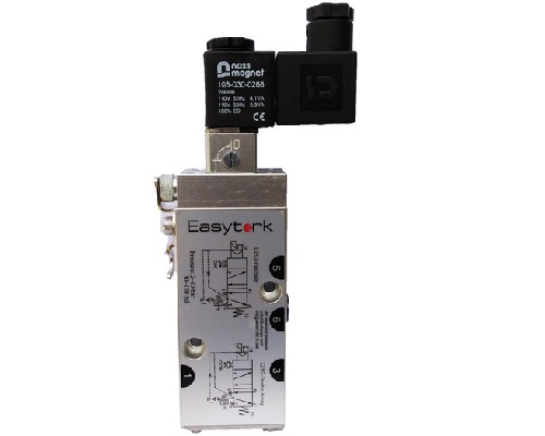
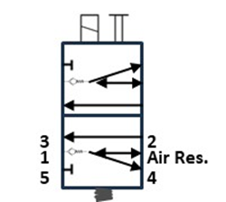
- Identify the ports
- P1 is the air supply; P2 and P4 serve the actuator; ports 3 and 5 are exhausts. Dedicated reservoir porting connects the stored-air supply.
- During normal operation
- The electrically operated 5/2 directional valve alternates supply between P2 and P4, exhausting the opposite actuator chamber while the reservoir charges.
- On loss of air supply
- The internal check valve prevents reservoir air from escaping back through the supply. Stored air is redirected to move the actuator to its configured fail position. Installation orientation sets fail-open or fail-close operation.
Engineering guide: how the control paths work →
For installation, use the model-specific technical documents and IOM.