
Direct rotary motion.
A clear path to torque.
Understand how a vane actuator converts air pressure into valve rotation, and why torque through the full stroke matters.
Compressed air becomes rotary motion
A pneumatic rotary actuator turns compressed-air energy into rotation. Quarter-turn valves commonly move through 90 degrees between their end positions. Pressure is the air-supply condition; torque is the turning effort delivered to the valve stem.
The vane is already moving in the direction you need
In an Easytork vane actuator, pressure acts on the vane inside a sealed chamber and produces rotation directly. There is no piston-to-gear conversion in the torque-producing mechanism. This rotary-to-rotary architecture is the starting point for understanding the product, rather than a linear-to-rotary mechanism added to a linear actuator.
Follow the force through the mechanism
Pneumatic pressure acts directly on the vane surfaces and produces torque. The effective leverage distance X is measured from the pivot point to the effective force location; the effective surface area is the active vane surface producing torque.
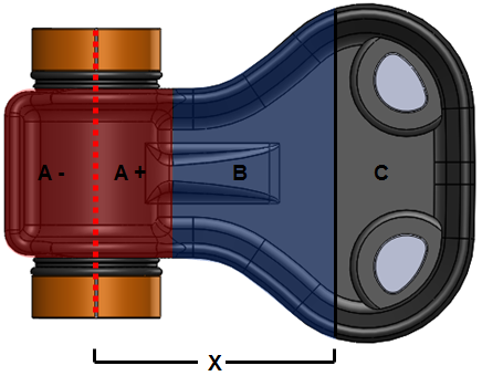
Conceptually, vane torque is pneumatic pressure × effective surface area × effective leverage distance X. At constant pressure, the effective area and X remain constant through rotation, giving an essentially constant double-acting torque output.
During double-acting operation, air is admitted to one side while the other side exhausts. Reversing those connections reverses rotation.
Torque depends on force and its effective leverage arm
Push on a door farther from its hinge and the same force produces more turning effort. The relevant distance is the perpendicular distance from the shaft axis to the force’s line of action, not simply the distance to the outside of the housing.
Torque = force × effective leverage distance X.
For a pressure-loaded surface, ideal torque = pressure difference × effective surface area × X.
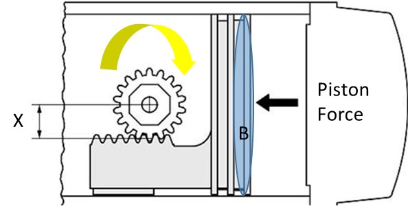
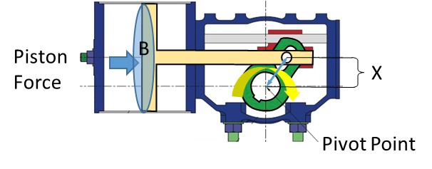
The drawings below show the handbook’s three actuator mechanisms. X denotes effective leverage distance in all three drawings. In the vane drawing, A+, A−, B and C label regions of the vane surface. In the rack-and-pinion and scotch-yoke drawings, B labels piston surface area. The drawings illustrate each mechanism; they are not drawn to a common scale.
Vane
Rack and pinion
Scotch yoke
Why a longer leverage arm can help a compact actuator
At the same pressure difference and effective force-producing area, a longer leverage arm produces more torque. Conversely, for a specified torque, more leverage can reduce the force and pressure-loaded area required. A vane uses the radial extent of its chamber to apply force directly around the output shaft. This is one reason the architecture can package useful torque in a compact assembly.
Compare published torque at the same available pressure and operating action, then compare the actual installation envelope, weight and full-stroke requirement. Product dimensions and published torque data establish torque per unit size.
Different mechanisms produce different torque profiles
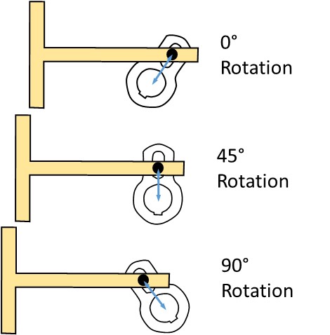
A vane turns directly. A rack-and-pinion actuator translates piston movement through a gear set. A scotch-yoke actuator translates piston movement through a yoke mechanism whose effective leverage changes with angle.
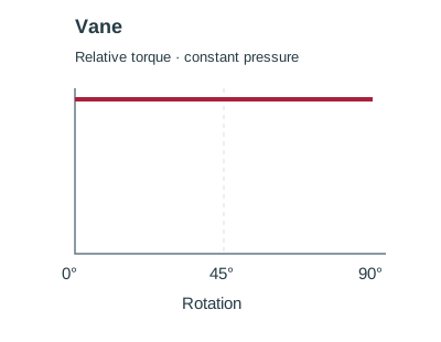
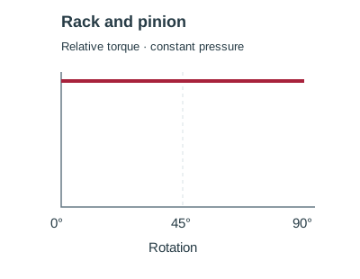
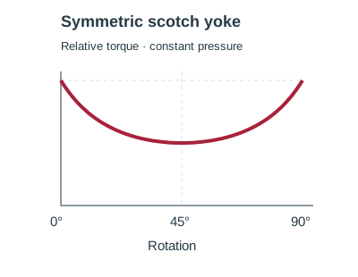
Conceptual double-acting profiles at constant pressure. The curves show shape, not equal torque or equal actuator size. The symmetric scotch-yoke example has its minimum at 45°; canted yokes and other linkage geometries have different profiles. Use the selected manufacturer’s torque curve for sizing.
Why the shape of the torque curve matters
At constant pressure, double-acting vane and rack-and-pinion arrangements can produce approximately constant torque through travel. A scotch-yoke profile varies with linkage geometry. Neither the maximum torque nor the name of the mechanism alone establishes suitability: compare the actuator output with the valve requirement throughout the stroke.
Put the mechanism in the context of the valve
Breakaway, running and seating loads can differ. A valve may need its highest torque near an end position rather than in the middle of travel. A useful selection therefore connects the valve torque requirement, available air pressure, required failure response and physical mounting arrangement.
Read the torque-sizing workflow → · Understand operating and fail functions →
Technical references
Rotork: symmetric and canted scotch-yoke profiles
Work through your application
Tell us the valve, available air pressure and operating duty. We can connect the mechanism to the actual selection.
Contact us →